 The final base in all its glory.
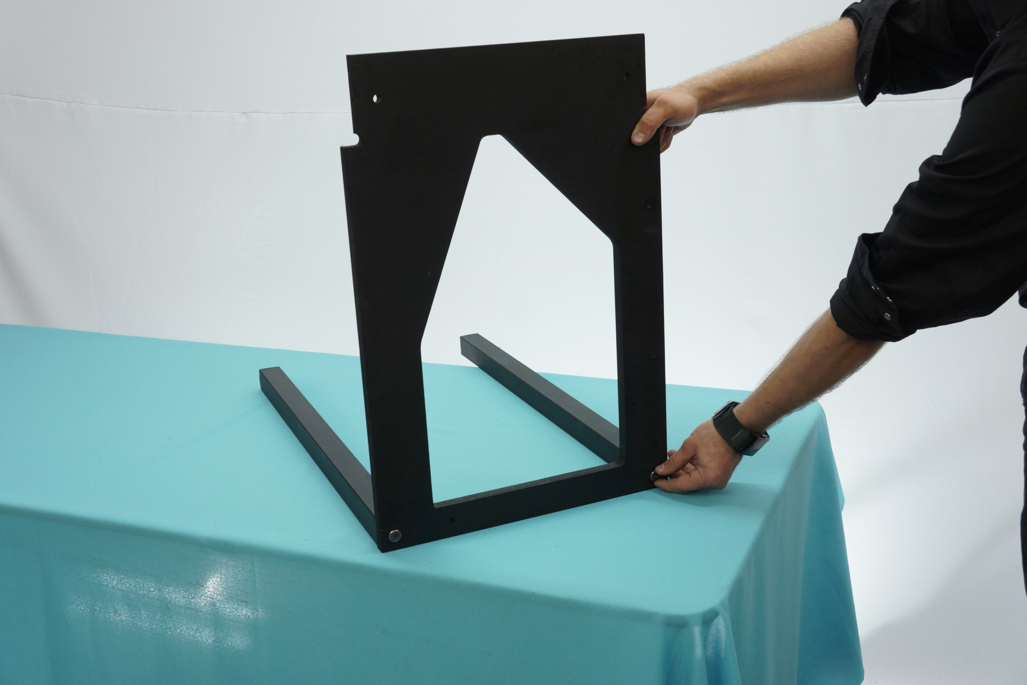 Attach the Base Bars (the thicker aluminum square bars) to a Side Plate with furniture bolts, as pictured. Finger tighten only. Then, attach the second Side Plate with furniture bolts, too. When you’re confident that the base rests evenly, wrench-tighten the bolts until they’re secure. Furniture bolts are turned with an Allen/Hex Wrench and have a very thin head.
 Orient the assembly as pictured.
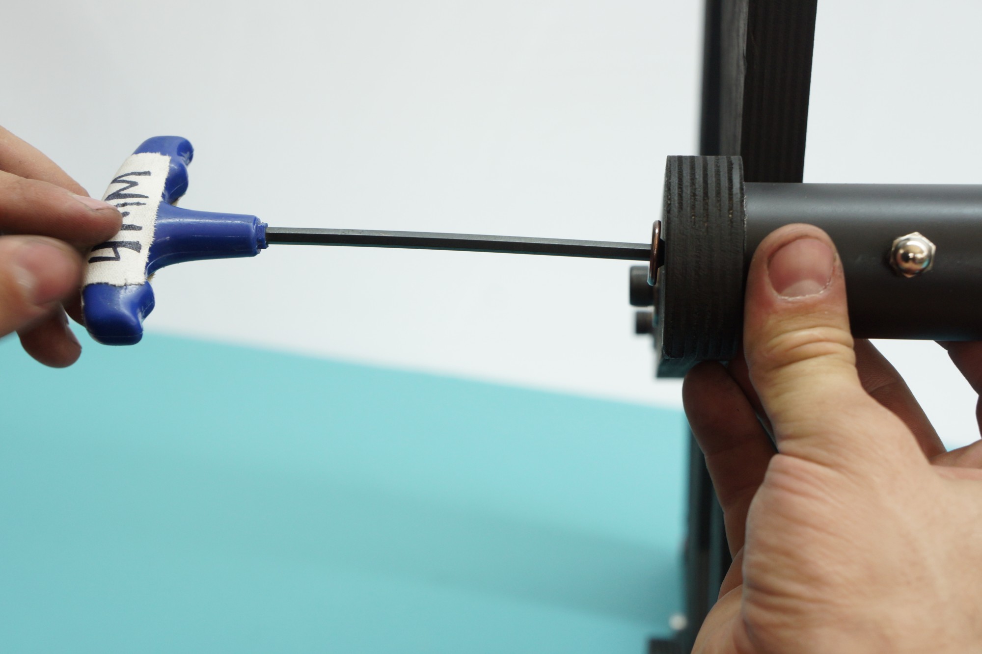
Insert a 40mm M8 bolt into a pulley, then spin a nut onto the bolt so it firmly contacts the pulley. Attach the pulley to the left side plate and cap it with an M8 flange nut. Tighten with a wrench.
The right side needs a pulley on the inside and outside of the side plate. Start with a 60mm M8 fully-threaded hex bolt. From left to right, your delicious pulley sandwich will go: Bolt > Pulley > Nut > WOOD > Nut > Pulley > Lock nut.
Tighten with a wrench when in place.
Spin a nut onto a 60mm M8 fully-threaded hex bolt until there’s about ¼ inch between the nut and the bolt head. Insert through the inside of the Right Side Plate. Secure with a nut. Cap the bolt with a flange nut, leaving about ¼ inch between the flange nut and M8 nut. This is where the bungee hook will attach.
 The left side only needs an attachment point on the inside. Insert a 40mm M8 bolt through the outside of the Left Side Plate. On the inside, secure with a flange nut, leaving ¼ inch between the flange nut and the nut you just installed. Another bungee will attach here.
With a 40mm M8 bolt through the outside of the Left Side Plate, attach the Cradle Lift Stop. Secure with a wingnut. Tighten the wingnut so the Cradle Lift Stop sticks firmly in place but still rotates out of the way.
 Apply felt to the inside relief of the Side Plates: it’s gentler on your books and highly recommended.
 Bolt the Cradle Runners to the Lifters with furniture bolts. Use a flat surface to ensure it’s even. Place the assembly into the the Scanner Base so the Lifters are sitting in the big relief holes in the Side Plates as pictured.
 Pop the F608ZZ flange bearings into both sides of all four lift arms. Finger-force should be good. Otherwise, persuade them with a deadblow hammer or Physics textbook.
 Put 50mm socket caps through both bearings of a Short Arm. Add a washer to the ends of the protruding bolts. Connect the Short Arm to the Lifter and Side Plate. Secure the bolts with flange nuts – just finger-tight for now.
 Insert a 50mm socket cap into the Right Long Arm Attachment Point hole (the head of the socket cap will be on the inside of the scanner). Add a washer. Spin a nut to the base. Cap with a flange nut.
 Once all the arms are in place, tighten the flange nuts with a wrench. Be careful. Only tighten until they feel firm. It’s possible to overtighten and put pressure on the bearings, locking them in place. Test the lift mechanism. It should feel easy and smooth. If it’s crunchy or stiff, you’ve overtightened. Side-to-side slop means you’ve not tightened enough. (Of course, without the bungees attached, it’ll feel heavy.)
 Drop an M8 nut onto the head of two eyebolts. Insert those eyebolts into the notched side of the Handlebar. The eyes of the eyebolts should run parallel with the Handlebar. Secure the eyebolts with a nut. Cap with an acorn nut. Acorns keep the eyebolts from poking your hands. They’re optional!
Bolt the Handlebar to both Long Lift Arms with furniture bolts. (The acorns face out, toward the user.) You’re done with the Base.