Lever Actuated Platens

Built a scanner? Started to build a scanner? Record your progress here. Doesn't need to be a whole scanner - triggers and other parts are fine. Commercial scanners are fine too.

Moderator: peterZ

Joe Reeser

Lever Actuated Platens

Post by Joe Reeser »

I'm new here so please be kind. :P I am getting ready to start my first build and I plan on using a lever to actuate the platen. I have several questions I would like as many answers to as possible from anyone who actually used such a set-up. I have read through aplumb300's thread and found it interesting. His lever is mounted through the center of the base. My concerns are mostly ergonomic in nature. I believe a more effective position (for a right handed person) would be for the lever to be mounted through the left side of the base and to be short enough to stay away from the center of the platen/book support while flipping pages. The center line linkage is quite simple and easy to build. Once the lever is moved away from the center line - not so much. I have worked out a crude design for the linkage and would like to know what the people here think. I will also be using his idea of putting the switch to trigger the cameras on the end of the lever. Has anyone used AP's design? If so, are there any recommended improvements? Things you would not change? Do you think it would be worth the trouble of moving the lever to the side vice the center? Any other comments?

The picture below shows the linkage in both the platen-up and platen-down positions. The platen-up position linkage is drawn with green lines. The platen-down position linkage is drawn with blue lines. I don't know if you will really be able to tell that in the picture. If it's not clear I can try to explain. Thanks for all the wonderful ideas here.

Image
Hasher
Posts: 77
Joined: 26 Sep 2009, 03:05

Re: Lever Actuated Platens

Post by Hasher »

I'm new here so please be kind

You would be suprised how friendly the locals are :lol:
User avatar
daniel_reetz
Posts: 2812
Joined: 03 Jun 2009, 13:56
E-book readers owned: Used to have a PRS-500
Number of books owned: 600
Country: United States
Contact:

Re: Lever Actuated Platens

Post by daniel_reetz »

I am traveling a lot over the next few weeks so I have little time for the forum, which is a shame because there are so many interesting new ideas here!

Looking at your lever design, I don't think I fully understand it. Why is it better than just having the single pivoting element that connects to the platen? What's the benefit of the added complexity?

I am very very very interested in compacting the whole book scanner into the smallest thing possible, and very interested in improved methods for lifting the platen in general. Looking forward to seeing your success here.
Joe Reeser

Re: Lever Actuated Platens

Post by Joe Reeser »

daniel_reetz wrote:Looking at your lever design, I don't think I fully understand it. Why is it better than just having the single pivoting element that connects to the platen? What's the benefit of the added complexity?
This was a rough design and to be honest I may not be using it at all. There were two objectives to this design: 1) to move the lever to the left side of the base. I felt this might be a better location than the center where it might get in the way of turning pages. 2) To reverse the action of the lever. I wanted to be able to pull down on the lever (with my left hand) in order to raise the platen. That's easy to do with the lever in the center. It's not so easy with the lever to the left side. I felt it was necessary because it just seems like a more natural motion to me. It is a lot of extra trouble to go to which is why I asked people who had used a lever whether they thought it would be worth the trouble. I'm an industrial engineer and a firm believer in making the machine conform to the operator rather than the other way around. I have since tweeked the design a little but I'm still unhappy with it. I have no experience with this kind of thing. My experience is in implementation rather than design.

I have read quite a bit here and completely understand your drive for miniaturization. Mine will be stationary so size, weight and travel are not constraints.

As far as lifting the platen, the easiest and most efficient way would probably be a linear actuator like this one:

http://www.firgelliauto.com/product_inf ... cts_id=230

Nine inches per second is surely too fast but I would think all the others offered would be too slow. A power supply:

http://www.firgelliauto.com/product_inf ... cts_id=103

and a speed controller makes it adjustable. http://www.firgelliauto.com/product_inf ... ucts_id=21

$250 seems a little steep to me just to raise a platen but perhaps someone will be interested.
Hasher
Posts: 77
Joined: 26 Sep 2009, 03:05

Re: Lever Actuated Platens

Post by Hasher »

Just wondering if a Linear Actuator is suitable for the task . Is it only a 2 position unit with extension and retraction or can you provide feedback to tell it when to stop driving . Just thinking if you have a thick book then it could overdrive the plattern down and damage the book scanner.
Joe Reeser

Re: Lever Actuated Platens

Post by Joe Reeser »

Hasher wrote:Just wondering if a Linear Actuator is suitable for the task . Is it only a 2 position unit with extension and retraction or can you provide feedback to tell it when to stop driving . Just thinking if you have a thick book then it could overdrive the plattern down and damage the book scanner.
That's a good question. It's surely possible to do feedback or barring that perhaps design it to stall at a certain down force to prevent damage. I haven't really looked into it very much to be honest. I ran across the site and thought it might be a good approach but it's just too pricey for the application, imo. If an automated setup is ever achieved, I would think something of the kind would be necessary. It's something to think about anyway.
Hasher
Posts: 77
Joined: 26 Sep 2009, 03:05

Re: Lever Actuated Platens

Post by Hasher »

If you look for second hand Actuators or rob from another machine that uses them you could save some cash. A way to get around the force problem is to use a spring which actuates (relieves the pressure )when the linear actuator gets to a predetermined force.
User avatar
daniel_reetz
Posts: 2812
Joined: 03 Jun 2009, 13:56
E-book readers owned: Used to have a PRS-500
Number of books owned: 600
Country: United States
Contact:

Re: Lever Actuated Platens

Post by daniel_reetz »

Joe Reeser wrote:There were two objectives to this design: 1) to move the lever to the left side of the base. I felt this might be a better location than the center where it might get in the way of turning pages. 2) To reverse the action of the lever. I wanted to be able to pull down on the lever (with my left hand) in order to raise the platen. That's easy to do with the lever in the center. It's not so easy with the lever to the left side. I felt it was necessary because it just seems like a more natural motion to me. It is a lot of extra trouble to go to which is why I asked people who had used a lever whether they thought it would be worth the trouble. I'm an industrial engineer and a firm believer in making the machine conform to the operator rather than the other way around. I have since tweeked the design a little but I'm still unhappy with it. I have no experience with this kind of thing. My experience is in implementation rather than design.
Well, I love the idea and I think you're on the right track. The platen is still the least-best engineered thing on these designs. Handle placement is an issue because it can cause torque on the linear slides or racking if they're not real precise, and having scanned hundreds of books, I can say for certain that a lever I could just push down on with my left arm would be a real benefit VS the present handle designs. They are not bad, but they are not great.

For my next scanner (which is going to be a normal-sized desktop scanner) I am going to try to implement either a foot pedal or a lever like you describe. I hope you end up working on it before I do (which may be months from now) because I'd like to learn from what you do...
User avatar
rob
Posts: 773
Joined: 03 Jun 2009, 13:50
E-book readers owned: iRex iLiad, Kindle 2
Number of books owned: 4000
Country: United States
Location: Maryland, United States
Contact:

Re: Lever Actuated Platens

Post by rob »

About the design pictured at the top of the post, you have four bars. One bar, the really short one, could be eliminated by just cutting a slot in the bar it attaches to, and attaching that bar directly to the platen. Since that bar describes an arc, you can easily determine how long the slot has to be. Assuming you can raise the vertical support so that the bar describes an equal angle at the top and bottom of the platen movement (36 degrees, by my calculations), the slot should be slightly over 1 3/8" long.

You could even eliminate the first two bars, because the bar attached to the vertical support achieves your purpose: pushing down on it will lift the platen. Of course, it's not very convenient. You can attach the end to a string or wire which leads to a foot pedal or to a secondary bar which you operate by hand, and you can attach the string/wire anywhere along the right side of the bar -- remembering that the closer the string attaches to the vertical support pivot, the more force you will need.

Alternatively, replace all the bars with string and pulleys.

Just an idea :)
The Singularity is Near. ~ http://halfbakedmaker.org ~ Follow me as I build the world's first all-mechanical steam-powered computer.
Joe Reeser

Re: Lever Actuated Platens

Post by Joe Reeser »

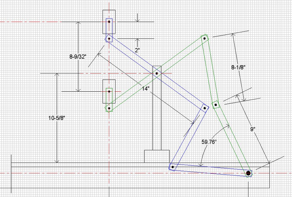
Well, I've been working on the design and maybe I have something a little more workable. I'll post a pic here with measurements for anyone who cares. I have assumed the lever would start out perpendicular to the base and swing down through an arc of about 75 degrees toward the center. At any rate that is what I was aiming for with the first lever on the back. This design will put a significant side load on whatever mechanism is used to suspend the platen. It could also put a significant torque load on it as well depending upon how far behind the platen the attach point for the mechanism is located. I was planning on using the twin PVC post design from the Cratylus build. I would substitute Schedule 80 PVC for the twin columns as the wall thickness is greater and it is stiffer. This should be able to handle any side or torque loads applied and has the advantage of being gray (at least generally) and unlikely to contribute to glare in the images taken.

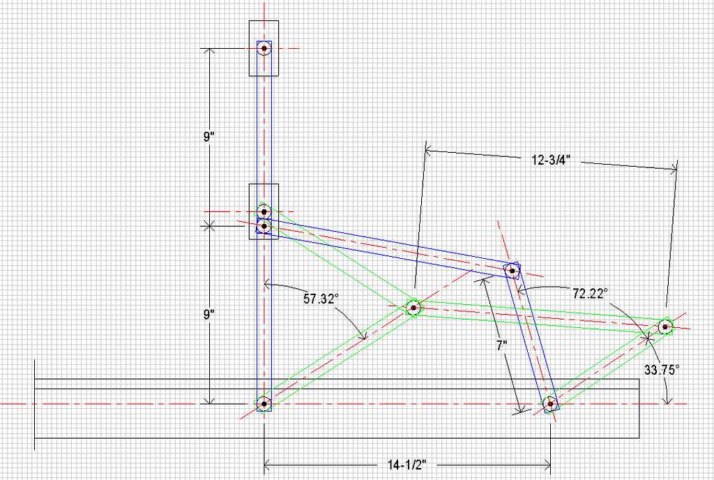
With this design the angular travel of the actuation lever can be varied by changing the length of the 7" lever shown in the sketch. If the length of this lever is changed to 9" then a parallelogram is set up and the angular travel will be the same as the center linkage, in this case about 57 degrees. Gradually shortening the lever towards 7" will result in ever greater travel of the handle.

With the center linkage being straight, that is the two 9" pieces in a straight line, an over-center stop could be easily incorporated so that the platen could be locked at the top for changing or positioning books on the cradle.

The total lift of the cradle with this design is 8 9/32". I was shooting for 8 1/4 and I figure that's close enough. We're not going to the moon here. lol If more lift is desired, the center links simply need to be lengthened the appropriate amount.

Any suggestions or criticism is welcome.


Image
Post Reply