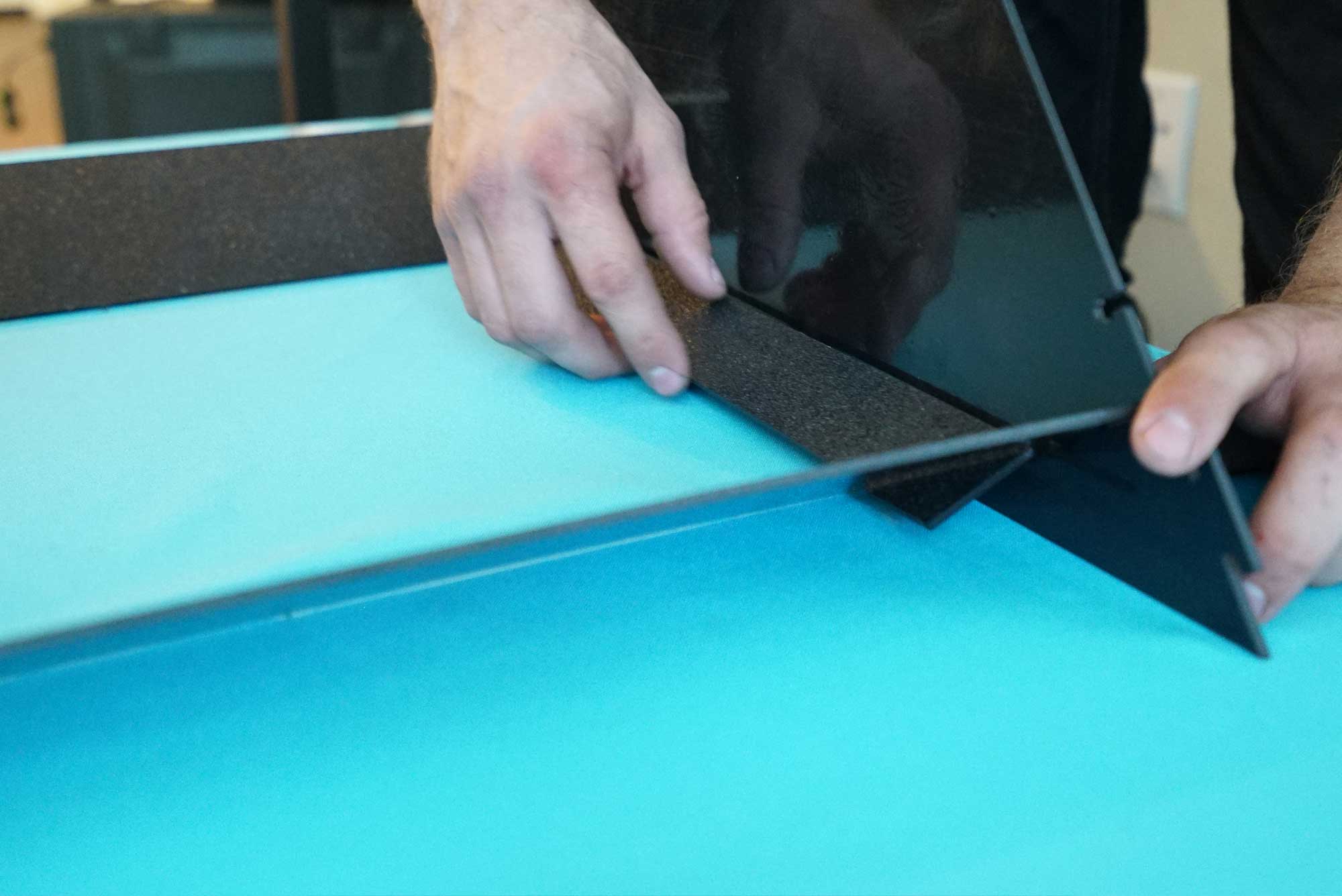
Grab a Large Baffle. Each large baffle has a slot on either side for insertion into the front and back plates. When seated, it looks like this:
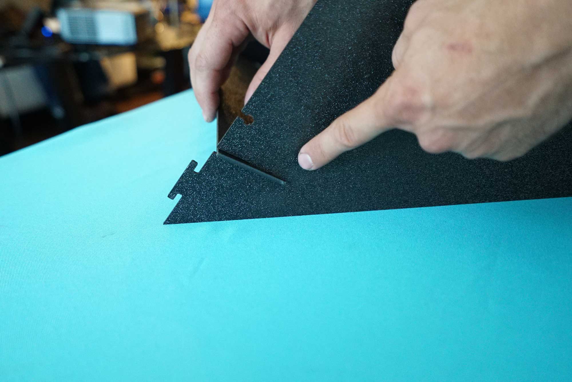
If you’re good, you can slide it into the front and the back plate at the same time.

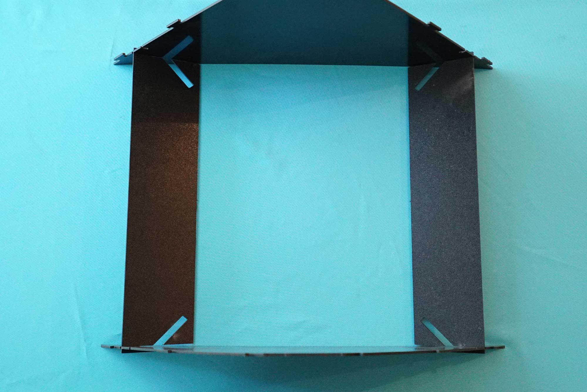
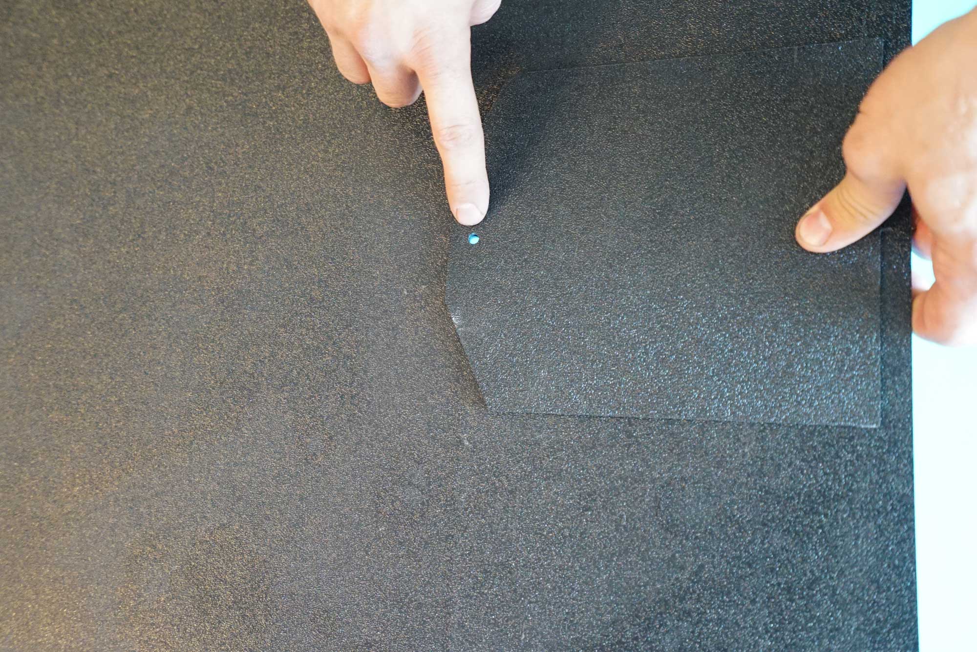
Next, do the same on the opposite side, and you’ll end up with something that looks like this — note the oblong open slots:
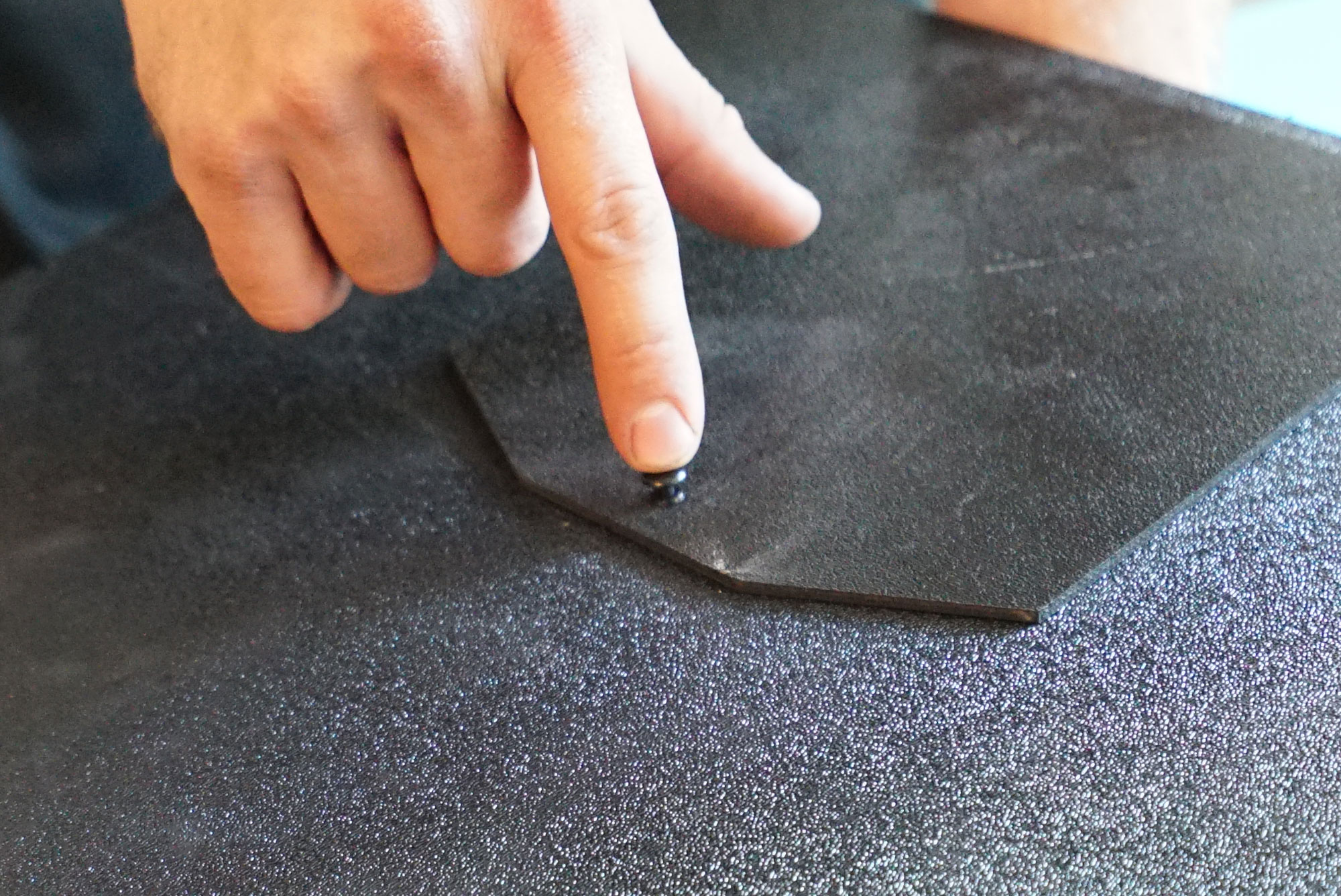
The small baffles have a locating tab on the side that prevents them from falling out when they are installed. Be sure to orient them as pictured.
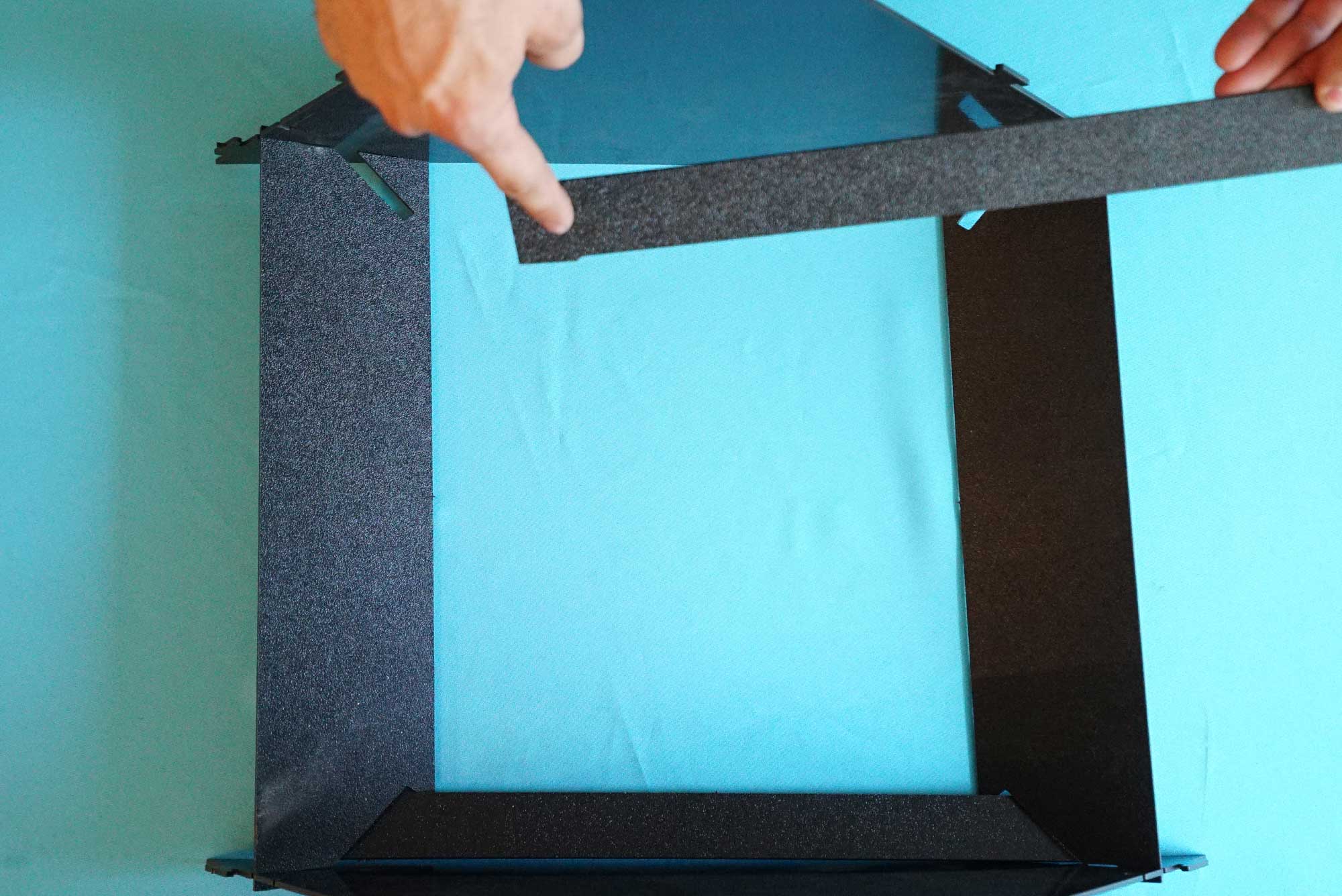
Insert the small baffles into the oblong slots in the large baffles. Set this assembly aside for the moment.
Line up the holes on the Camera Access Door and the side plate.
Attach doors to side plates using plastic rivets. Insert the rivet until it seats in the hole, then press down the plunger to fix it in place.
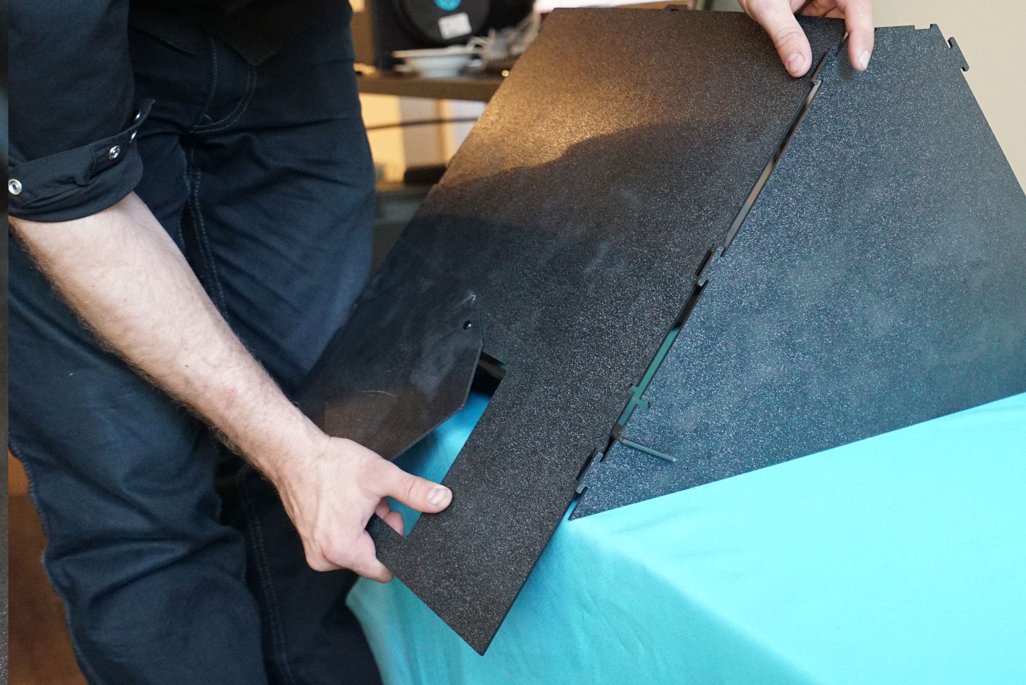
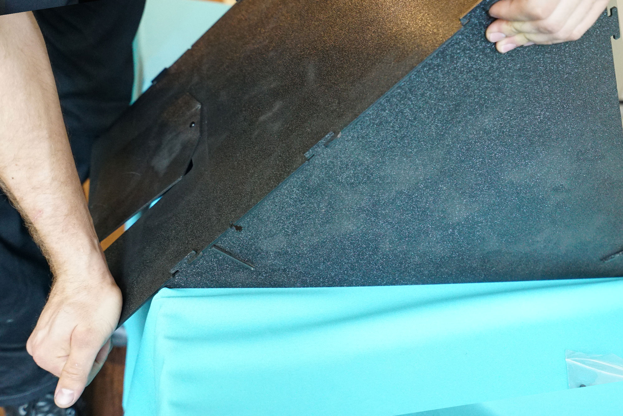
Attach side plates. They are easiest to install if you by hang them off the side of a table, as pictured.
Lock the tabs with a downward pull toward the floor.
It’s now time to permanently secure the side plates. There is a hole in the side plate and a tab/slot arrangement on the front and rear plates. Insert a screw through the side plate, and a nut in the cross in the front/rear plate, and tighten the screw down with a 2mm wrench to lock the side plates in place.

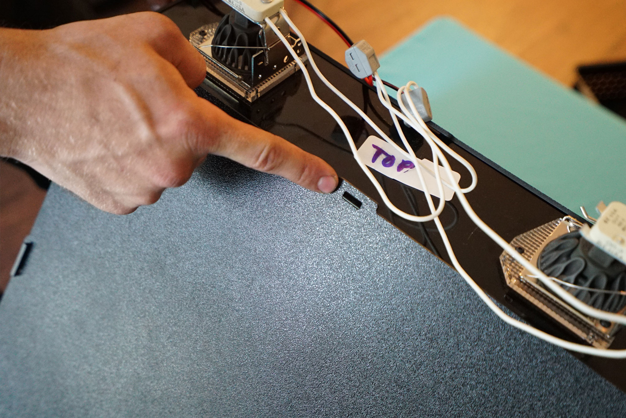
Set the lighting assembly aside for a moment. Locate the FR4 Light Mount. Check that the top of piece is labeled, otherwise, orient it as pictured.
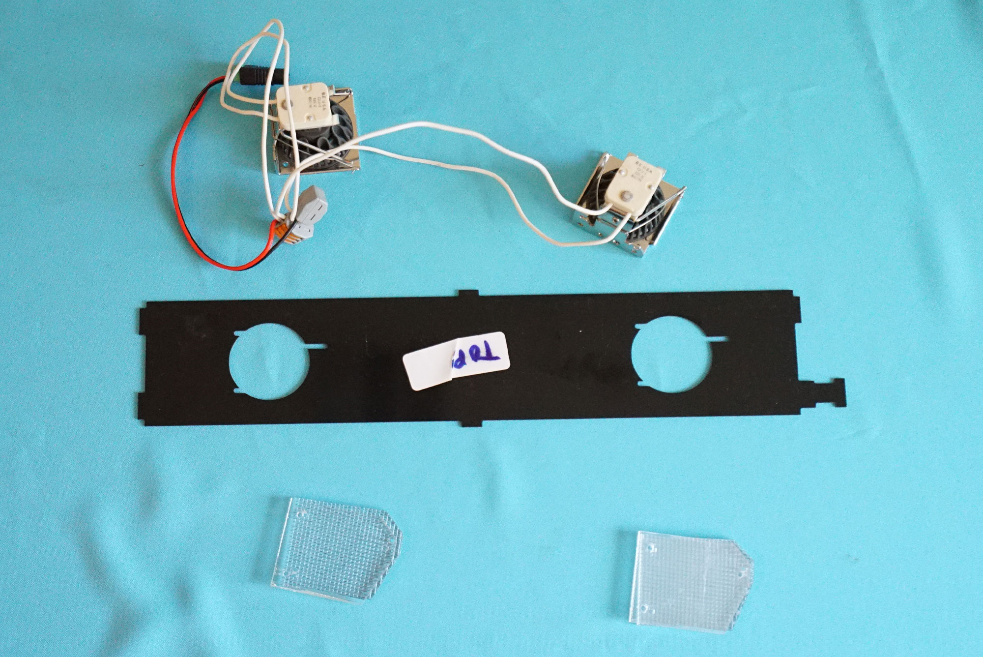
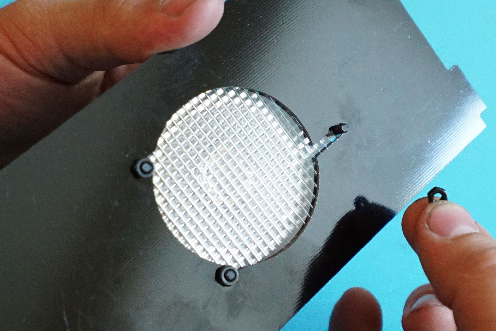
The optics must be installed in a particular order, as pictured. The optics are roughly rectangular, with a long side and a short side. Stack them up as pictured. Also, the optics are covered in a polyethylene protective coating. Be sure to remove the covering from the optics before installation.

Drop screws into the holes in the back of the Lamp Sockets, so that they hang free like this:
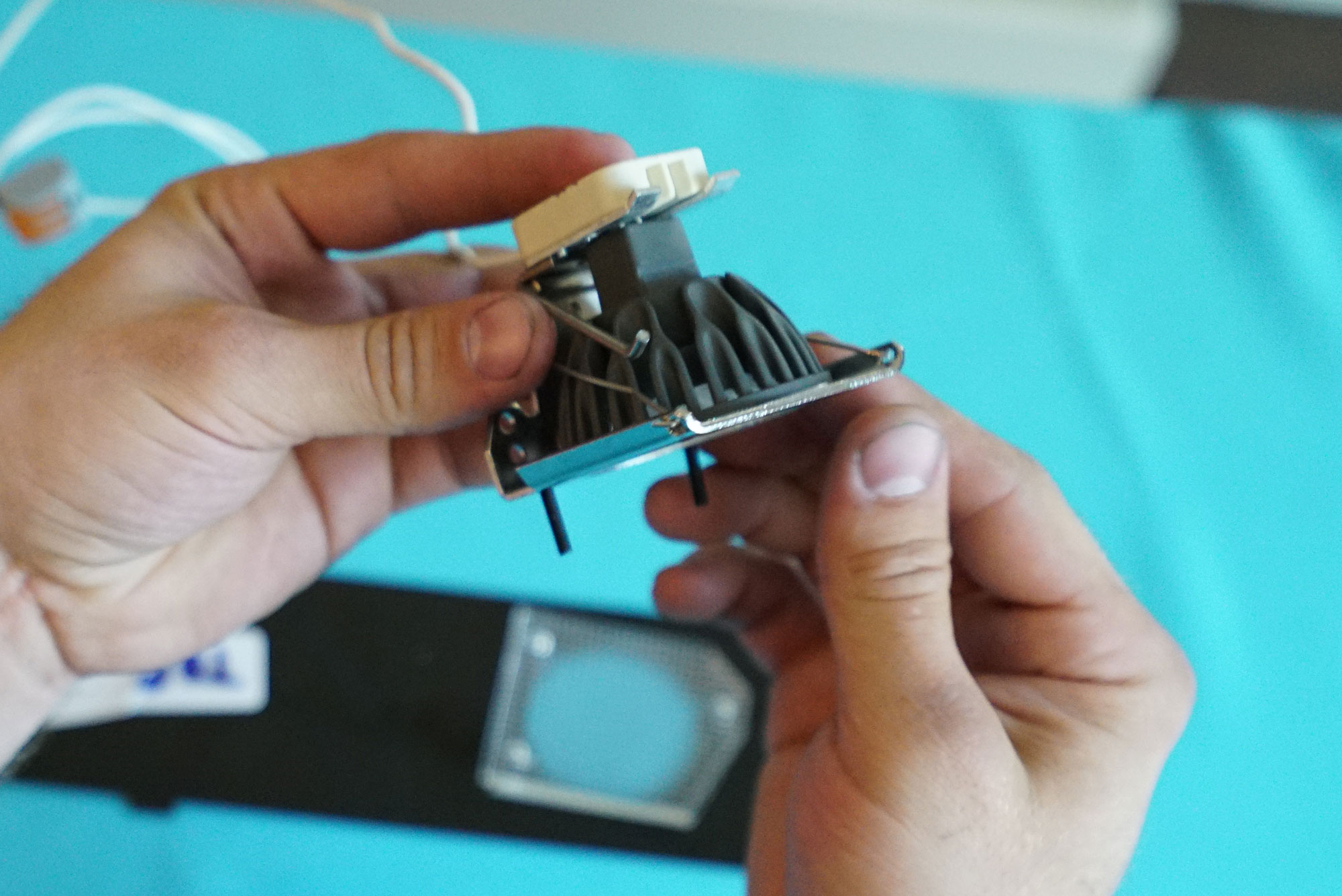
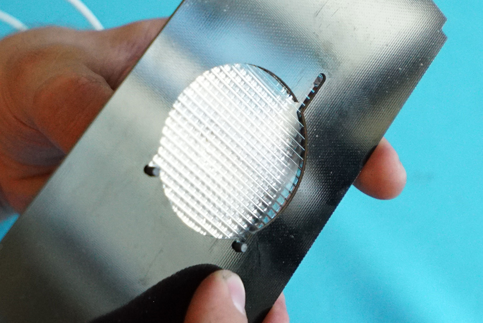
The optics have holes which mate with the now-dangling screws. Slide them together.

Now, put the same two screws through the FR4 Lighting Mount to secure the optics to the FR4 Lighting Mount. Insert a third screw through the optics to secure the other side.
Tighten down all sides with matching nuts. Repeat these operations for the other set of optics and the other Lamp Socket.
Attach the female barrel jack to the FR4 Lighting Mount with a black zip tie as pictured.
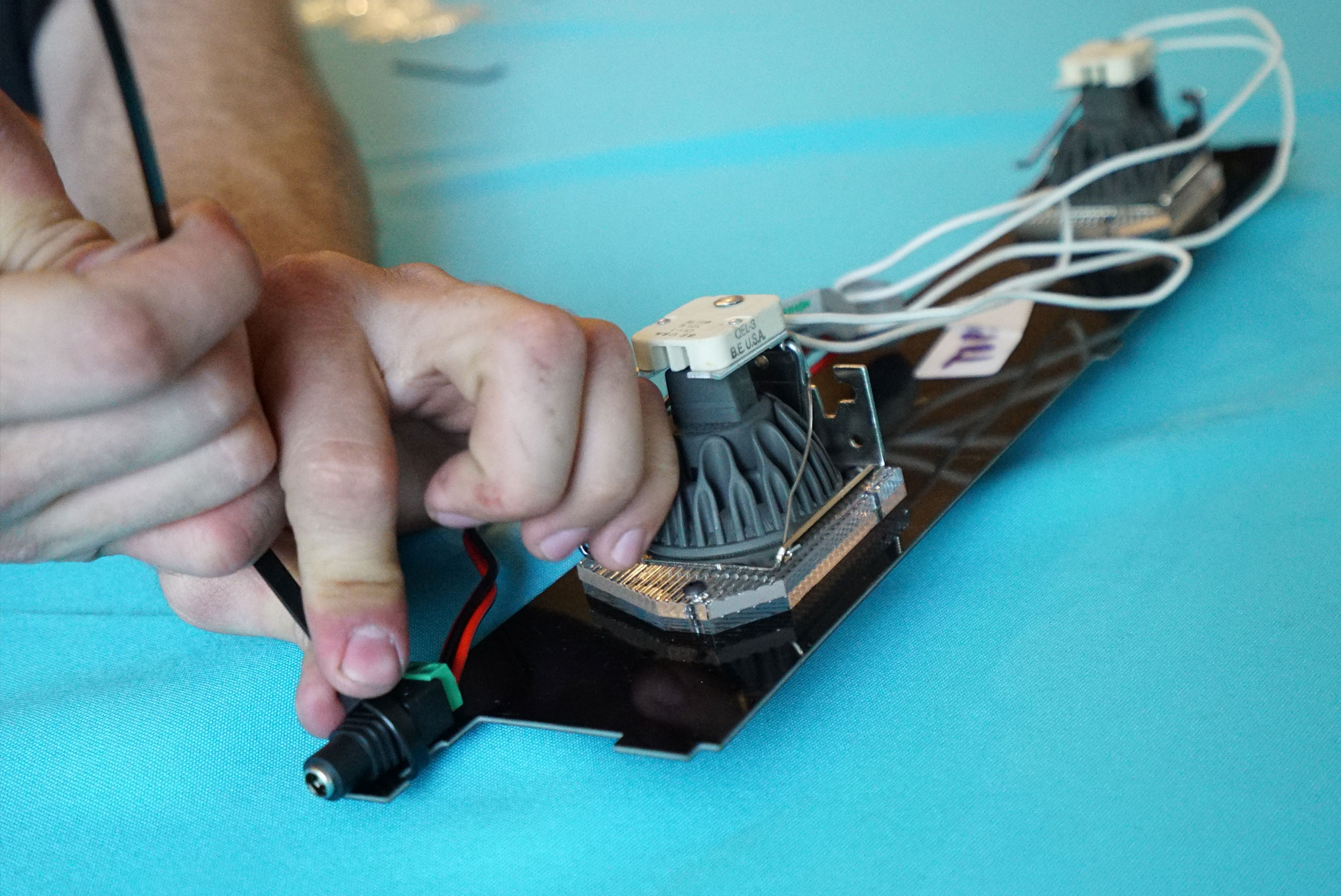
The FR4 Lighting Mount Assembly is now complete. Mount it on the top of the ABS plastic assembly you made earlier by inserting the central tabs into the central slots of the ABS plastic assembly.
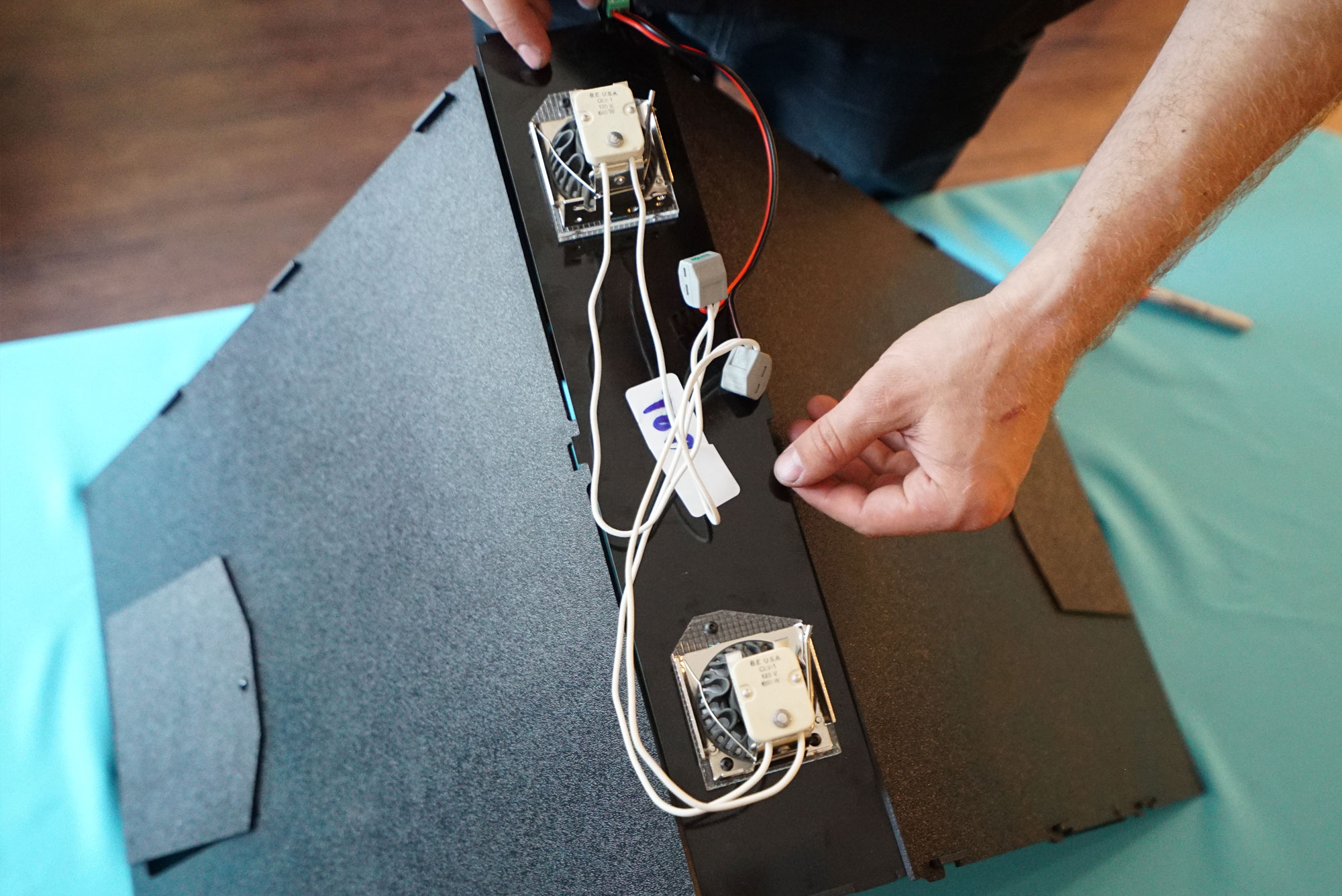
Check that the tabs are well-seated in the slots.
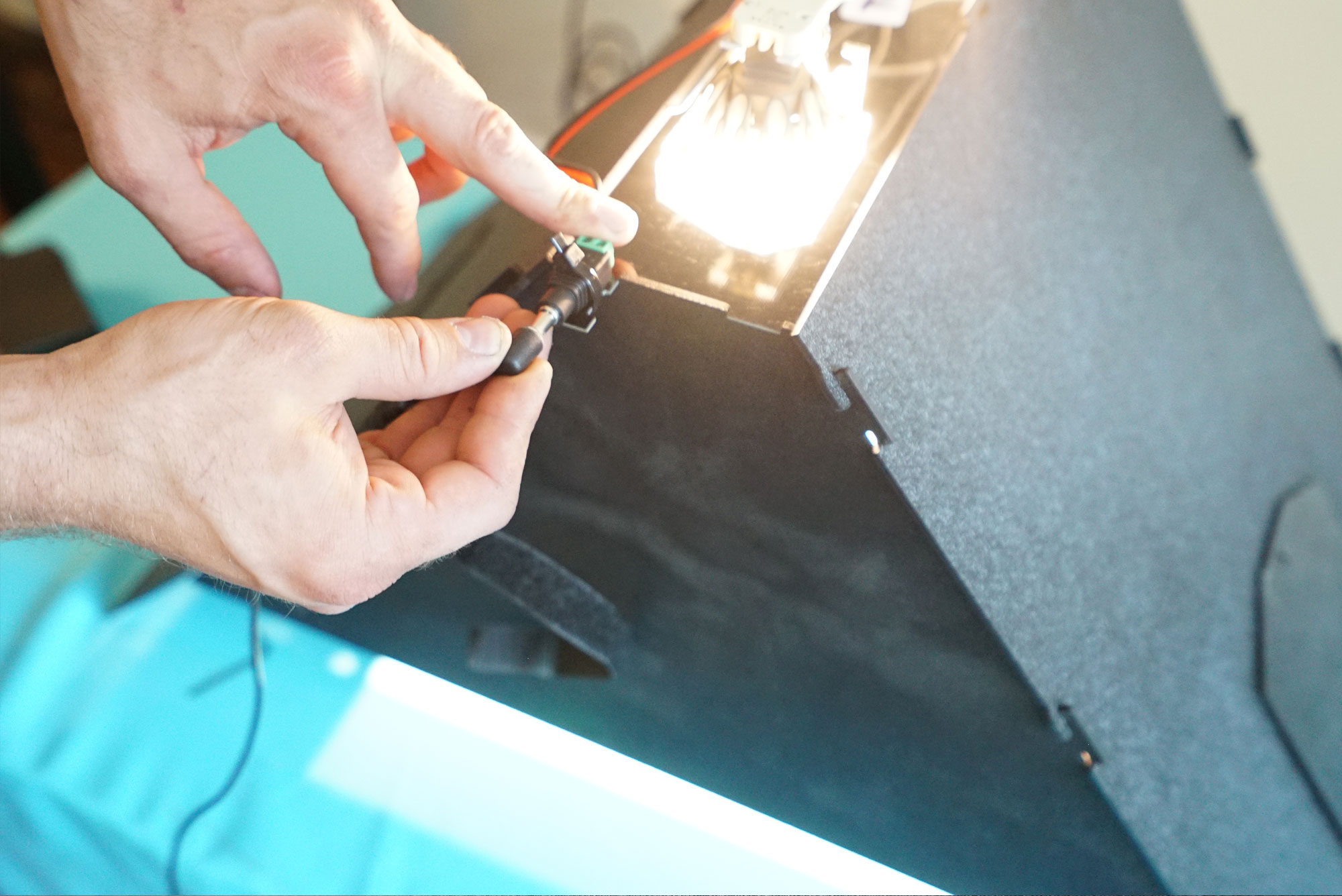
Double-check that the LEDs are wired in parallel and that the connections all look solid. Connect the power supply. If your LEDs light up, everything is correct. Done.
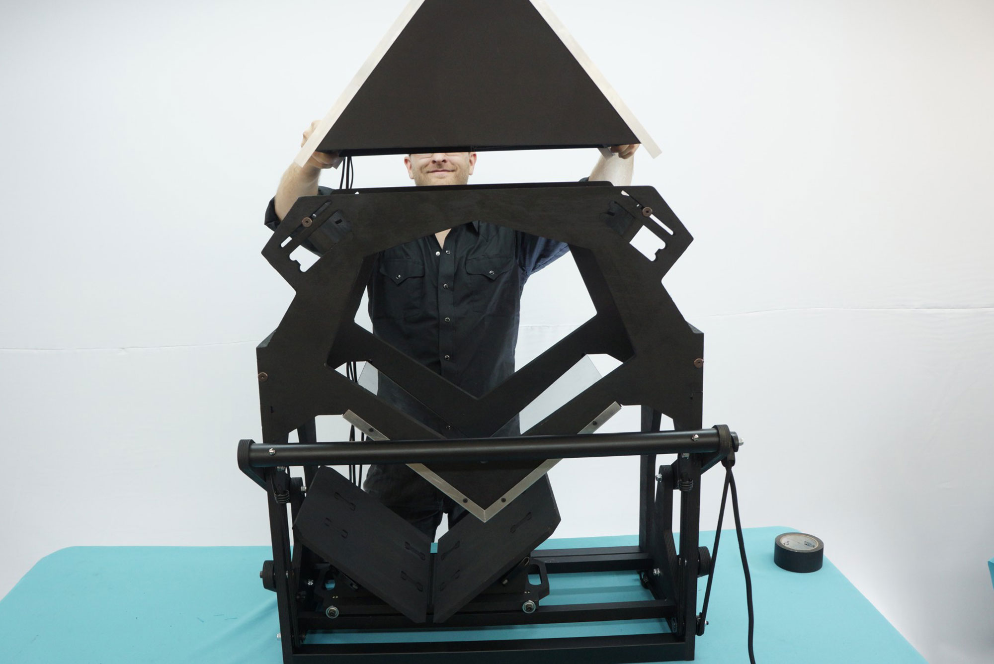
Place the Lighting Module on top of the book scanner base (note — this image shows a mockup/prototype lighting module, but installation is the same. Set it on top. Done.).